DIRSIG4 and DIRSIG5 support in-scene moving geometry, which allows objects to be dynamically positioned and allows for accurate "thermal scaring" effects, motion distortions, and the easy creation of time-lapsed imagery. This motion model uses a key-frame approach or what we usually refer to as the "delta movement" approach. The user supplies an initial state at an absolute time. The user also specifies a series of changes (translation, scale and rotation) relative to the last know state as a function of time. The code will linearly interpolate between the supplied times to generate any additional positioning information when needed. By using this delta approach, everything is relative to an initial state and it becomes easy to shift the absolute time at which a movement occurs.
Reference Frame
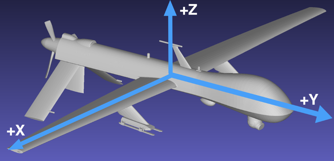
The primary coordinate system in DIRSIG is the East-North-Up (ENU), where the ENU axes correlate to X, Y and Z, respectively. The reference frame for motion models in DIRSIG is as follows:
-
The "forward" axis is the +Y axis.
-
The "up" axis is the +Z axis.
-
The remaining axis (+X) is the "right" wing (follows the right-hand rule).
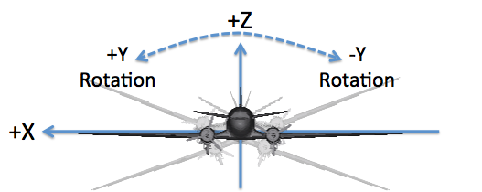
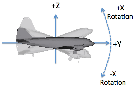
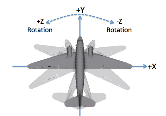
How do roll, pitch and yaw relate to this motion frame?
-
The "roll" axis is Y, and a positive angle corresponds to a right wing down or left wing up rotation.
-
The "pitch" axis is X, and a positive angle corresponds to a "nose up" rotation.
-
The "yaw" axis is Z, and a positive angle corresponds to a counter-clockwise rotation as viewed from above.
|
|
The DIN 9300 and ISO 1151–2 conventions also follow a right-hand rule but define the +X axis as the "forward" or "roll" axis, the +Y axis as the "right wing" or "pitch" axis and the +Z axis as the "down" or "yaw" axis. Special care must be taken to know which convention is being used when rotation data is being imported. |
|
|
The motion defines the location and orientation of the object it is associated with. For platform motion in sensor plugins it is important to know what the default camera orientation is relative to the vehicle. For example, in the BasicPlatform plugin the default orientation of cameras is looking down the -Z axis. |
Format Details
The movement file is composed of three major sections:
-
The Options section describes options about the motion and visibility of the associated object.
-
The Initial Position section specifies the positioning of the instance at a given absolute time.
-
The Movement Entries section contains a series of "delta change" records, which specify forward chaining modifications to the initial position.
DIRSIG_MOV = 1.0

OPTIONS {
    START_HIDDEN = FALSE
    END_HIDDEN = FALSE
}

INIT_POSITION {
    TRANSLATION = 0.00, 20.00, 10.00
    SCALE = 1.0, 1.0, 1.0
    ROTATION = 0.0, 0.0, 1.57
}

MOVES {
    #      dSec  dTx  dTy  dTz  dSx  dSy  dSz  dRx  dRy  dRz
    MOVE = 360, 5.0. 0.0, 0.0, 0.0, 0.0, 0.0, 0.0, 0.0, 0.0
    MOVE = 360, 5.0. 0.0, 0.0, 0.0, 0.0, 0.0, 0.0, 0.0, 0.0
    MOVE = 360, 3.0. 0.0, 0.0, 0.0, 0.0, 0.0, 0.0, 0.0, 0.0
    MOVE = 360, 4.0. 0.0, 0.0, 0.0, 0.0, 0.0, 0.0, 0.0, 0.0
    MOVE = 360, 5.0. 0.0, 0.0, 0.0, 0.0, 0.0, 0.0, 0.0, 0.0
}
|
|
The order of the axis rotations is the same as that employed in the Object Database file. That order is is Z, then Y, then X and cannot be changed. |
Initial Position
The INIT_POSITION section define the date and time when the initial
state of the object is defined. This initial state includes the initial
location, scaling and rotation of the object. All subsequent changes or
"moves" are relative to this initial position and orientation:
INIT_POSITION {
    TRANSLATION = 0.00, 20.00, 10.00
    SCALE = 1.0, 1.0, 1.0
    ROTATION = 0.0, 0.0, 1.57
}
|
|
In DIRSIG 4.5 and later, the date and time do not need to be
included in the INIT_POSITION section. When the date and time
are not provided, this initial state is assumed to correspond to
the simulation reference date and time.
|
The initial position can optionally include the date and time that all the "moves" are relative to:
- Local Date and Time
-
The
DATE,LOCAL_TIMEandGMT_OFFSETvariables must be provided. - GMT Date and Time
-
The
DATE,GMT_TIMEandGMT_OFFSETvariables must be provided. - ISO-8601 Date and Time
-
The
DATE_TIMEvariable must be provided (this option is available in the DIRSIG 4.6 and later releases)
|
|
For backwards compatibility with DIRSIG3, the GMT_OFFSET
variable is positive West of Greenwich rather than the
commonly used East of Greenwich convention. The ISO-8601
date/time supplied via the DATE_TIME variable follows the
common positive East of Greenwich convention (as specified
by the ISO standard).
|
For example, all three of the following are equivalent:
INIT_POSITION {
    DATE = 6 23 2002
    GMT_OFFSET = 5.000
    LOCAL_TIME = 12.000
    TRANSLATION = 0.00, 20.00, 10.00
    SCALE = 1.0, 1.0, 1.0
    ROTATION = 0.0, 0.0, 1.57
}
INIT_POSITION {
    DATE = 6 23 2002
    GMT_OFFSET = 5.000
    GMT_TIME = 17.000
    TRANSLATION = 0.00, 20.00, 10.00
    SCALE = 1.0, 1.0, 1.0
    ROTATION = 0.0, 0.0, 1.57
}
INIT_POSITION {
    DATE_TIME = 2002-06-23T12:00:00.0000-05:00
    TRANSLATION = 0.00, 20.00, 10.00
    SCALE = 1.0, 1.0, 1.0
    ROTATION = 0.0, 0.0, 1.57
}
Movement Entries
The MOVES section contains a list of records that define a forward
chaining sequence of changes to the initial state. Each line defines an
additive change in location, scale and rotation at a time relative to
the previous state. In the example, the first MOVE record defines
the changes to the initial state 360 seconds after the initial time
(the simulation reference time, in this example). The second MOVE
entry defines the state 360 seconds after the first entry (or 360 +
360 = 720 seconds after the initial state) and does so by modifying the
location, scale and rotation state resulting from the first MOVE entry.
The third MOVE entry modifies the state resulting from the second entry,
and so on.
|
|
In this example, all the MOVE entries have the same delta time,
but that is not a requirement. For example, the use of irregular
time steps allows the user to describe varying velocities
(acceleration).
|
|
|
Specifying a negative or zero delta time is invalid. That is because it makes it possible for the user to describe two (or more) unique location and/or orientation states for the same time. Clearly an object cannot be in two (or more) locations and/or orientations at the same time. If the model sees a negative delta time, it issues an error. If the model sees a zero delta time, it issues a warning where it informs you that the delta time has been changed to a very small positive time. |
To understand the motion defined by this example, consider the first record:
    #      dSec  dTx  dTy  dTz  dSx  dSy  dSz  dRx  dRy  dRz
    MOVE = 360, 5.0, 0.0, 0.0, 0.0, 0.0, 0.0, 0.0, 0.0, 0.0
At 6 minutes (360 seconds) after Noon (the initial time specified in
the INIT_POSITION section), the object has moved +5 meters in the X
direction. There has been no change in the objects Y or Z positions.
Likewise, the scale and rotation of the object have remained unchanged.
Therefore the location is now 5, 20, 10, the scale is still 1, 1, 1
and the rotation is still 0, 0, 0.
Now consider the next record (which is the same as the first, in this case):
MOVE = 360, 5.0, 0.0, 0.0, 0.0, 0.0, 0.0, 0.0, 0.0, 0.0
At 12 minutes after Noon (360 + 360 = 720 seconds or 12 minutes)
the instance has moved another 4 meters in the positive X direction.
Therefore, the location is now 10, 20, 10, the scale is still 1, 1, 1
and the rotation is still 0, 0, 0.
As previously mentioned, DIRSIG will use linear interpolation between
specified positions. If the current simulation time is 12:09 PM, then
DIRSIG will interpolate halfway between the first (12:06 PM) and the
second (12:12 PM) entries. Thus, the position will have an X translation
of 5.0 + 2.5 = 7.5, resulting in a location of 7.5, 20, 10.
|
|
DIRSIG uses a "flat" extrapolation. Any time before the INIT_POSITION
will be equal to the INIT_POSITION state. Similarly, any time after
the last specified MOVE will be equal the state resulting from the
last specified MOVE (and, of course, all the deltas leading up to it).
|
|
|
There is nothing wrong with a negative scale delta, which would indicate that the overall scale is decreasing for a given step. However, a series of decreases in the scaling can eventually result in a negative scale, at which point an error will be issued. |
|
|
The rotation deltas above are defined in radians and interpolation
for values greater than Pi radians is ambiguous. Attempting
to supply such a MOVE will result in an error message. The
solution is to supply an intermediate MOVE (see Examples
for more discussion).
|
Visibility Options
The MOV file is commonly used as a conduit to import vehicle motion from the SUMO traffic simulator into the DIRSIG model. In that case (and many others), vehicles start from specific locations at some time during the simulation and arrive at their destinations at some other time. It is desirable for some users to not have these vehicles stationary at the start location until they start driving or stationary at the end location after they finish driving. In the past, various strategies have been employed to accomplish this:
-
The
timewindowattribute can be used in the GLIST file with a given<dynamicinstance>to specify the relative times during which the instance is visible. If that time window is set to the window during which the instance is in motion, then it will be hidden for times outside that time window. The downside to this approach is that motion and visibility information is split across two files. -
The manual "teleportation" approach has been adopted by many users. This approach involves setting the initial Z location of the object to be well below the ground by specifying a large, negative Z component in the
INIT_POSITION. When the vehicle starts to move, the firstMOVEentry quickly moves the vehicle up to the starting position. This is accomplished by injecting a newMOVEentry a fraction of a second before the the firstMOVEentry that handles the required Z translation. A similar approach can be used at the end of the path to move the vehicle back below the ground. The downside to this approach is that theINIT_POSITIONandMOVESmust be carefully modified.
Although both of these methods have worked, a set of specific options
were added in the 4.6.2 release to explicitly control the visibility of
the object before the first MOVE and after the last MOVE entry:
OPTIONS {
    START_HIDDEN = FALSE
    END_HIDDEN = FALSE
}
The default values for these two variables (if the options do not appear
in the MOV file) is FALSE. A value of TRUE for the START_HIDDEN
variable means that the object will be hidden until the time defined
by the first MOVE entry. Likewise, A value of TRUE for the END_HIDDEN
variable means that the object will be hidden after the time defined
by the last MOVE entry.
Examples
Linear Velocity
Linear velocity can be computed simply as the delta translation divided by the delta time. Consider the two entries below:
    ...
    MOVE = 1.00, 10.0, 0.0, 0.0, 0.0, 0.0, 0.0, 0.0, 0.0, 0.0
    ...
For time during the window defined by this entry (the exact time
will be dependent on the previous entries), the object will be traveling
at 10 m/s in the +X direction. That is because the second MOVE entry
specifies a change in X of +10 meters over a time period of 1 second.
Angular Velocity
Because the delta rotations are limited to values of +/- Pi, it is
tricky to create full rotations or define rotational rates. For
example, to create a constant 360 degree (2 Pi) rotation over a
period of 1 second (a rate of 1 Hz), you need to break the rotation
movements into two parts: one for the first Pi radians of rotation
and one for the second Pi radians of rotation. Consider the set
of two MOVE descriptions provided below:
    MOVE = 0.50, 0.0, 0.0, 0.0, 0.0, 0.0, 0.0, 0.0, 0.0, -3.141592654
    MOVE = 0.50, 0.0, 0.0, 0.0, 0.0, 0.0, 0.0, 0.0, 0.0, -3.141592654
The first MOVE rotates the object Pi radians during the first 0.5
seconds, and the second MOVE rotates the object another Pi radians
during the second 0.5 seconds. This results in 2Pi radians of
rotation during 1 second. The negative sign on the delta Z rotation
angles result in clock-wise rotation under the right-hand rule
employed throughout DIRSIG.
|
|
Because of the "flat interpolation" scheme employed, the object will stop rotating after 1 second. To have that object rotate at the same rate for N seconds, the user must duplicate these two entries N times in order to define the motion for all N seconds. |