Overview
Instrument "mounts" are key feature of the DIRSIG4 platform model and is supported by the DIRSIG5 BasicPlatform plugin. The primary role of a "mount" is to provide a location where one or more "instruments" can be attached to the "platform". The mount object is analogous to camera hole or camera ball on a real aircraft or a location on a satellite bus. The DIRSIG mount models can be used not only to locate instrument mount locations ) within the platform, but also to point the instrument(s) relative to the platform. The secondary role of the mount objects is to support "dynamic pointing" or "scanning" of the instrument(s) as a function of time so that more complex acquisition geometries and methodologies can be modeled. For example, command data for pivoting a camera ball relative to the aircraft it is attached to can be modeled via a mount object.
Reference Frame
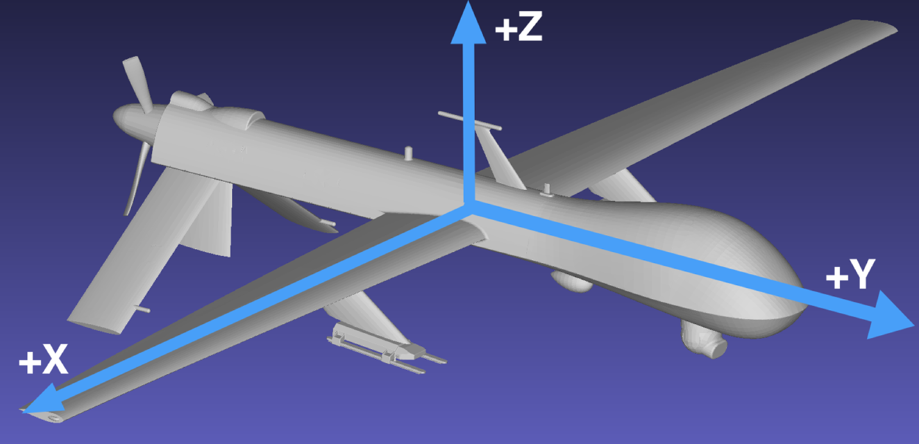
The primary coordinate system in DIRSIG is the East-North-Up (ENU), where the ENU axes correlate to X, Y and Z, respectively. The reference frame for motion models in DIRSIG is as follows:
-
The "forward" axis is the +Y axis.
-
The "up" axis is the +Z axis.
-
The remaining axis (+X) is the "right" wing (follows the right-hand rule).
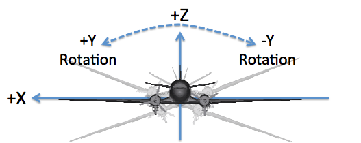
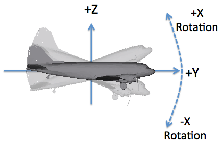
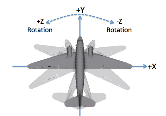
How do roll, pitch and yaw relate to this motion frame?
-
The "roll" axis is Y, and a positive angle corresponds to a right wing down or left wing up rotation.
-
The "pitch" axis is X, and a positive angle corresponds to a "nose up" rotation.
-
The "yaw" axis is Z, and a positive angle corresponds to a counter-clockwise rotation as viewed from above.
|
|
The DIN 9300 and ISO 1151–2 conventions also follow a right-hand rule but define the +X axis as the "forward" or "roll" axis, the +Y axis as the "right wing" or "pitch" axis and the +Z axis as the "down" or "yaw" axis. Special care must be taken to know which convention is being used when rotation data is being imported. |
|
|
The motion defines the location and orientation of the object it is associated with. For platform motion in sensor plugins it is important to know what the default camera orientation is relative to the vehicle. For example, in the BasicPlatform plugin the default orientation of cameras is looking down the -Z axis. |
Reference Sequences
In addition to knowing what the reference axes are, you must know if the rotations are used as part of an extrinsic or intrinsic sequence:
- extrinsic
-
Every rotation in a sequence is relative to a global coordinate system.
- intrinsic
-
A rotation in a sequence refers to the last rotated coordinate system, with the first rotation relative to the global coordinate system.
|
|
The various motion models support interpreting Euler angles as either an extrinsic or intrinsic rotation sequence. Some motion models support selecting between extrinsic or intrinsic sequences while others are hard-coded to support only one or the other. |
Angle Conventions
The DIRSIG4 platform model has a nominal heading in the +Y direction, so across-track scanning is along the X-axis (or about the Y-axis) and along-track scanning is along the Y-axis (or about the in X-axis). Note that this old holds true if the attachment between the mount and the platform does not introduce a rotation of the mounts coordinate frame (which only happens when the user deliberately manipulates the mount attachment). For more information about the coordinate conventions consult the Coordinates Systems document and the Affine Transform document.
Translation
In DIRSIG4, mounts were limited to platform-relative rotation only. In the DIRSIG5 BasicPlatform plugin the ability to model platform-relative translation was added for a select set of data-driven mounts:
Jitter
Each mount has the option to include jitter, which will add deviations to the nominal pointing of the current mount. This feature allows the user to incorporate unprogrammed motion into the platform-relative pointing. This could be used to emulate shaking in a camera ball on an aircraft or flex in mounts used to bolt instruments to the platform. Like the jitter support in other parts of the DIRSIG model, the user can specify temporally uncorrelated and correlated jitter on a per-axis basis.
|
|
Jitter can be configured for all mount types, including the "static" mount. |
Clock
Most of the dynamic mounts have a "clock" associated with them. This clock has the same interface as those associated with components like a focal plane, which allows the clock to be setup as either an independent clock or one slaved to the master clock on the platform. This clock defines the frequency that a dynamic mount will repeat the scan pattern. For example, a sinusoidal "whisk" pattern with a clock set to 30 Hz will repeat the full sweep (across and back to the starting position) 30 times per second.
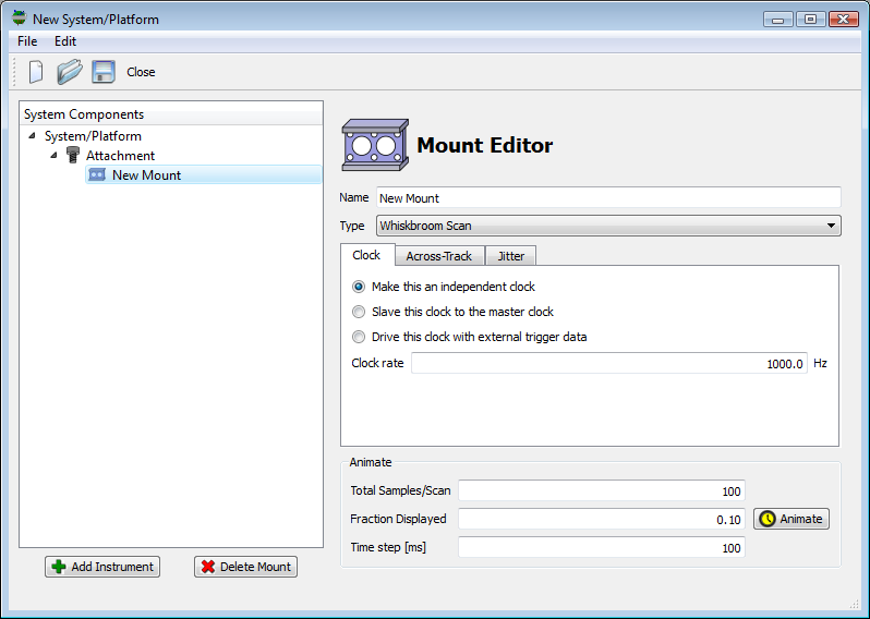
|
|
The option to supply an external trigger file to a dynamic mount is currently disabled because the concept does not make sense in the context of the frequency of a periodic scan pattern. |
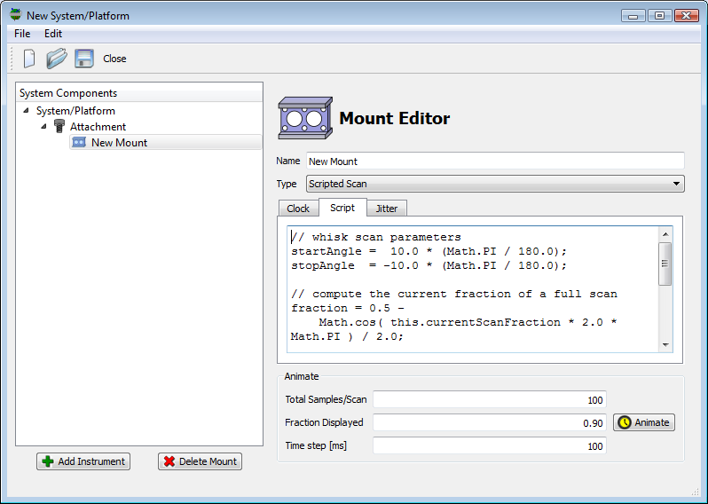
Visualization
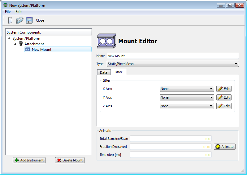
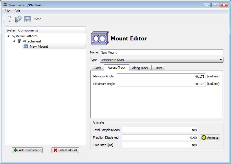
The Mount Editor in the graphical user interface allows the user to visualize a dynamic mount by plotting the along-track and across-track pointing angles as a function of time. The Animate panel at the bottom of the Mount Editor allows the user to control the visualization parameters.
- Total Samples/Scan
-
This parameter controls the total number of points plotted if the entire scan is visualized. Depending on the complexity of the scan pattern, the default value may need to be increased to provide an accurate visualization of the scan pattern.
- Fraction Displayed
-
At each time step, a fraction of the scan pattern is displayed. As the pattern is animated, this fraction will trace out the full scan pattern. Setting this fraction to
1.0will plot the entire scan pattern, but using a smaller fraction combined with animation also allows the user to visualize the entire scan pattern. - Time step [ms]
-
This parameter controls the speed of the animation. A smaller time step will cause the animation to step faster.
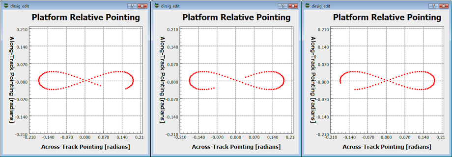
The images below show different points in time in the animation of
a "Lemniscate" scan. The Fraction Displayed was increased to 0.90
so that more of the scan pattern could be visualized during each step.
Static (Fixed) Mount Models
The DIRSIG model currently supports only one fixed mount model.
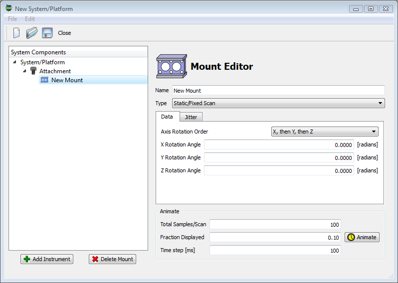
Static with Fixed Euler Angles
The "static" mount points the attached instrument(s) in a fixed direction with respect to the platform. The user defines this pointing direction via a set of constant right-handed X, Y and Z axis Euler rotation angles. The user must supply the order that the axis rotations are perform in (see the affine transform document for more information on Euler rotation operations). For example, the "rotation order" of "xyz" indicates to first apply the X rotation, then the Y rotation, then the Z rotation. This mount interprets the Euler angles as an extrinsic rotation sequence.
But default, the model configures a static mount with these pointing angles all set to zero, which results in the instrument pointing straight down out of the aircraft or satellite bus.
<mount> element in the .platform file for a static mount. <mount type="static" name="Static Mount">
<data rotationorder="xyz" angularunits="radians">
<xrotation>0</xrotation>
<yrotation>0</yrotation>
<zrotation>0</zrotation>
</data>Periodic (Scanning) Mount Models
The DIRSIG model currently supports several mount models that generate periodic pointing sequences.
Lemniscate
The "lemniscate scan" mount provides the user with a way to produce a "figure 8" style scan pattern. The user has control over the the along-track and across-track angular ranges.
|
|
The lemniscate scan pattern is sometimes employed to scan a LIDAR system because of some desired pulse density properties that can be optimized based on the platform velocity. |
<mount> element in the .platform file for a lemniscate scan. <mount type="lemniscate" name="Lemniscate Scanner">
<data angularunits="radians">
<clock type="independent" temporalunits="hertz">
<rate>1</rate>
<offset>0</offset>
</clock>
<acrosstrack>
<minimumangle>-0.135</minimumangle>
<maximumangle>0.135</maximumangle>
</acrosstrack>
<alongtrack>
<minimumangle>-0.0675</minimumangle>
<maximumangle>0.0675</maximumangle>
</alongtrack>
</data>Related Demos
-
The LemniscateScanMount1 demo provides a working example of a periodic lemniscate scan mount.
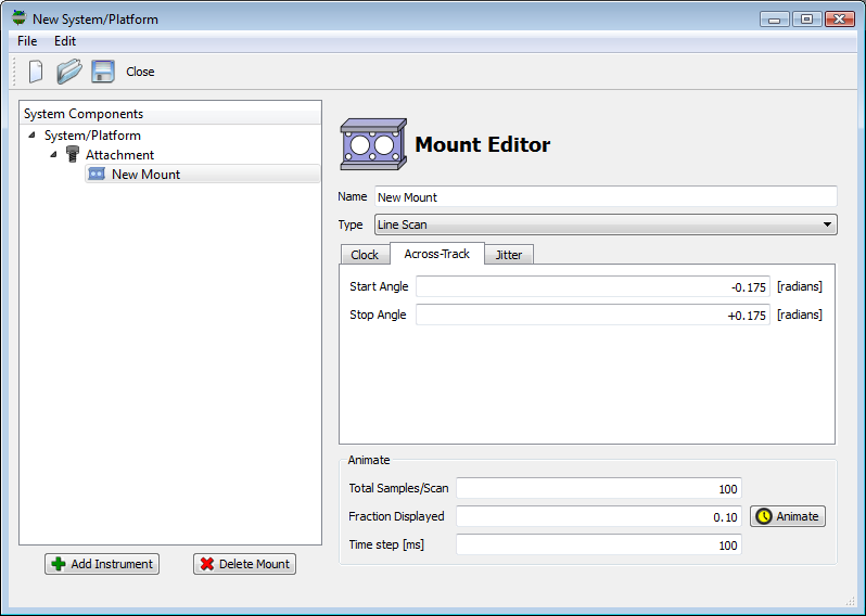
Line
The "line scan" mount provides the user with a constant angular velocity scan in the across-track direction. The scan direction follows a right-hand
|
|
The line scan pattern has infinite acceleration at the edges of the scan range (it turns around to scan back in the other direction instantaneously). If you want a scan that slows down and reverses direction, use the Whisk mount. |
<mount> element in the .platform file for a line scan mount. <mount type="line" name="Line Scanner Mount">
<data angularunits="radians">
<clock type="independent" temporalunits="hertz">
<rate>1</rate>
<offset>0</offset>
</clock>
<scanrange>
<start>-0.135</start>
<stop>0.135</stop>
</scanrange>
</data>Related Demos
-
The LineScanMount1 demo provides a working example of a periodic line scan mount.
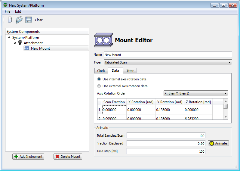
Tabulated
The "tabulated" mount allows the user to model an arbitrary, periodic
scanning mount by inputting XYZ Euler rotation angles as a function
of "scan fraction". The "scan fraction" ranges from 0 to 1, and
is a way to convey where the mount is in a scan independent of time
or the scan rate. A scan fraction of 0 is the start of the scan
and a scan fraction of 1 is the end of a scan. As a result, a
fraction of 0.5 is the middle of the scan. For a continuous
repeating scan, then the state at 0 and 1 should be the same.
The user only needs to supply known time/rotation pairs and the
model will linearly interpolate rotations for intermediate times.
|
|
Supplying scan fractions less than 0 or greater than 1 results in an error. |
|
|
The tabulated mount is an ideal choice for a scan pattern that doesn’t match one of the functional scan patterns provided by the other built-in mount models. It also allows the user to incorporate measured scan patterns. |
The user has two choices for how the angle vs. scan fraction data is supplied.
-
Using "internal" data, where the angles vs. scan fraction data is stored within the
.platformfile. -
Using "external" data, where the angles vs. scan fraction data is stored within an external file (for example,
conical_data.txt).
The reason that this mount supports either internal or external data is to better support different scenarios. A fixed scan pattern that never changes from collection to collection can be stored as "internal" data. If the pointing is specific to a specific collection, then it might make more sense to store that data "external" to the platform file in order to avoid having multiple copies of platform files that simply vary in the command data driving the pointing.
In either case, the user must provided the axis rotation order. The choice of axis rotation order has a large impact on the resulting orientation (see the Affine Transform document for more information on the impact of rotation order). This mount interprets the Euler angles as an extrinsic rotation sequence.
Example: Conical Scan
To better explain how data can be supplied and used, consider the following example of a simple, constant angular velocity "conical scan" (this is the scenario captured in the TabulatedMount1 demo). Because the mount linearly interpolates between the supplied angles vs. scan fraction records, the entire scan (sweeping out the entire 360 degree arc of the cone perimeter) can be described with three entries:
conical_scan.txt file.0.0000 0.000 0.135 0.0000 0.5000 0.000 0.135 3.1415 0.9999 0.000 0.135 6.2832
The first column is the scan fraction, the second is the X-axis
rotation angle (radians), the third is the Y-axis rotation angle
(radians) and the fourth is the Z-axis rotation angle (radians). The
goal of out scan is to create a pattern that sweeps a full circle
about the Z-axis with a 0.135 radian (about 7.75 degrees) angle
formed between the pointing angle and the vertical (Z-axis).
-
The first entry rotates "out"
0.135radians about the Y-axis and then about the Z-axis 0 radians. -
The second entry rotates "out"
0.135radians about the Y-axis and then about the Z-axis \(\pi\) radians. -
The third entry rotates "out"
0.135radians about the Y-axis and then about the Z-axis \(2\pi\) radians.
The rotation order of "X, then Y, then Z" is critical in this case. Consult the affine transform document for more information on the impact of rotation order if this is unclear. Since the Y-axis rotation is the same for both entries, all scan fractions between them will be the same. However, what does change as a function of scan fraction is the Z-axis angle. The Z-axis rotation for each scan fraction between 0 and 1 will be a linear interpolation between 0 and 360 degrees. And since 0 degrees and 360 degrees are the same, we have created a continuous, constant angular velocity conical scan pattern.
|
|
The 2nd entry insures the "direction" of the Z rotation. |
<mount> element in the .platform file for a rotating, tabulated mount. <mount type="tabulated" name="Tabulated (Internal Data)">
<data rotationorder="xyz" angularunits="degrees">
<clock type="independent" temporalunits="hertz">
<rate>1</rate>
</clock>
<entry>
<fraction>0.0000000000</fraction>
<xrotation>0.0000000000</xrotation>
<yrotation>7.7349302343</yrotation>
<zrotation>0.0000000000</zrotation>
<xtranslation>0.0000000000</xtranslation>
<ytranslation>0.0000000000</ytranslation>
<ztranslation>0.0000000000</ztranslation>
</entry>
<entry>
<fraction>0.5000000000</fraction>
<xrotation>0.0000000000</xrotation>
<yrotation>7.7349302343</yrotation>
<zrotation>180.0000000</zrotation>
<xtranslation>0.0000000000</xtranslation>
<ytranslation>0.0000000000</ytranslation>
<ztranslation>0.0000000000</ztranslation>
</entry>
<entry>
<fraction>0.9999999999</fraction>
<xrotation>0.0000000000</xrotation>
<yrotation>7.7349302343</yrotation>
<zrotation>360.0000000</zrotation>
<xtranslation>0.0000000000</xtranslation>
<ytranslation>0.0000000000</ytranslation>
<ztranslation>0.0000000000</ztranslation>
</entry>
</data>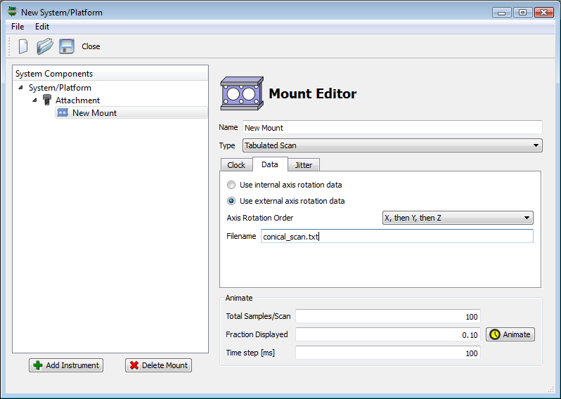
If you are setting up a tabulated mount from scratch and want to import data from an external file to be stored internally, simply right-click inside the table area and select the "Import" item from the menu. The format of the file to be imported or the external file is assumed to follow the conventions of the example file shown above.
Example: Translational Scan
The tabulated mount can also support translational scan motions.
Translation is introduced via the <xtranslation>, <ytranslation>
and <ztranslation> elements in the .platform XML file or via 3
additional columns in an external ASCII/Text data file. The
TabulatedMount2 demo features
a mount that translates in the +Y
direction, which is the default along-track direction (as long as the
mount to platform attachment doesn’t introduce any rotations). This
scan pattern linearly translates in +Y and then resets to the origin
before resetting:
<mount> element in the .platform file for a translating, tabulated mount. <mount type="tabulated" name="Tabulated (Internal Data)">
<data rotationorder="xyz" angularunits="degrees">
<clock type="independent" temporalunits="hertz">
<rate>1</rate>
</clock>
<entry>
<fraction>0.0000000000</fraction>
<xrotation>0.0000000000</xrotation>
<yrotation>0.0000000000</yrotation>
<zrotation>0.0000000000</zrotation>
<xtranslation>0.0000000000</xtranslation>
<ytranslation>0.0000000000</ytranslation>
<ztranslation>0.0000000000</ztranslation>
</entry>
<entry>
<fraction>0.9999999999</fraction>
<xrotation>0.0000000000</xrotation>
<yrotation>0.0000000000</yrotation>
<zrotation>0.0000000000</zrotation>
<xtranslation>0.0000000000</xtranslation>
<ytranslation>-10.0000000000</ytranslation>
<ztranslation>0.0000000000</ztranslation>
</entry>
</data>turtle_scan.txt file.0.0000 0.00 0.00 0.00 0.00 0.00 0.00 0.9999 0.00 0.00 0.00 0.00 -10.00 0.00
Related Demos
-
The TabulatedMount1 demo provides a working example of a periodic mount that performs a conical scan.
-
The TabulatedMount2 demo provides a working example of a periodic mount that performs a translational scan.
Whisk
The "whisk scan" mount scans the attached instrument(s) in the across-track direction. The DIRSIG4 platform models have a nominal heading in the +Y direction, so across-track scanning is an Y axis rotation. At the present time, the X and Z rotations are constant and 0 valued. The "whisk scan" mount is a dynamic mount, so the description includes a scan rate that defines the rate at which the mount sweeps and entire scan. The across-track scan covers user-defined angular range using a sinusoidal function.

<mount> element in the .platform file for a whisk mount. <mount type="whisk" name="Whisk Mount">
<data angularunits="radians" angularmethod="righthanded">
<clock type="independent" temporalunits="hertz">
<rate>1</rate>
<offset>0</offset>
</clock>
<scanrange>
<start>-0.135</start>
<stop>0.135</stop>
</scanrange>
</data>Related Demos
-
The WhiskScanMount1 demo provides a working example of a periodic whisk scan mount.
Non-Periodic (Pointing) Mount Models
The DIRSIG model also supports several mount models that handle non-periodic pointing sequences.
|
|
The non-periodic mounts are not currently available in the
graphical user interface. They must be manually configured by
hand-editing the XML .platform file.
|
Tracking
The "tracking mount" will always point at a designated piece of scene geometry. It can handle moving platforms, moving target geometry, and offset instrument mount attachments. To specify what piece of scene geometry is tracked by the mount, the user must provide the name of a unique instance inside an GLIST file.
XML Description
The excerpt below shows the configuration of this mount in the
.platform file. The mount must be of type attribute must be
assign tracking.
<mount type="tracking" name="Tracking Mount">
  <data>
    <targetname>EnemyFighter</targetname>
    <targetoffset>
      <point><x>0.0</x><y>0.0</y><z>0.0</z></point>
    </targetoffset>
  </data>
  <attachment>
    ...
  </attachment>
</mount>|
|
Because this mount is not periodic, there is no concept of a "clock" for this mount. |
The key parameter is the <targetname>, which indicates the name
of a specific geometry instance in the scene for this mount to
track. The mount will point at the local origin of that instance.
If the user wishes to offset that stare point within the object
instance, then the <targetoffset> can be used to provide that
offset. For example, to stare at the nose of a aircraft, the offset
can be used to shift the stare point from the local origin of the
aircraft (usually near the center of mass) to the nose.
Inside the GLIST file, there must be an instance
declared with the same name attribute (in this case, EnemyFighter).
This optional attribute can be assigned to both static and dynamic
instance types, but it must be unique for the scene. Having multiple
instances with the same name will result in an error.
<object>
  <basegeometry>
    <gdb><filename>aircraft.gdb</filename></gdb>
  </basegeometry>
  <staticinstance name="EnemyFighter">
    <translation>
      <geodeticlocation>
        <latitude>43.12</latitude>
        <longitude>-78.45</longitude>
        <altitude>300</altitude>
      </geodeticlocation>
    </translation>
    <rotation>
      <cartesiantriple><x>0</x><y>0</y><z>45</z></cartesiantriple>
    </rotation>
    <scale>
      <cartesiantriple><x>1</x><y>1</y><z>1</z></cartesiantriple>
    </scale>
  </staticinstance>
</object>
Related Demos
-
The TrackingMount1 demo provides a working example of using this mount mount to follow a moving scene object from a moving imaging platform.
Commanded
This mount is very similar to the Tabulated mount, except that the primary variable is time rather than scan fraction. This makes it easier to configure a scenario like a camera ball that rotates to specific locations at specific times. This mount interprets the Euler angles as an extrinsic rotation sequence.
XML Description
The excerpt below shows the configuration of this mount in the
.platform file. The mount must be of type attribute must be
assign commanded.
<mount type="commanded" name="Direct Pointing">
  <data rotationorder="xyz" angularunits="degrees">
    <entry>
      <datetime type="absolute">2008-07-01T12:00:00.0000-04:00</datetime>
      <xrotation>0.0</xrotation>
      <yrotation>0.0</yrotation>
      <zrotation>0.0</zrotation>
    </entry>
    <entry>
      <datetime type="absolute">2008-07-01T12:00:01.0000-04:00</datetime>
      <xrotation>+2.0</xrotation>
      <yrotation>+2.0</yrotation>
      <zrotation>0.0</zrotation>
    </entry>
    ...
    <entry>
      <datetime type="absolute">2008-07-01T12:00:04.0000-04:00</datetime>
      <xrotation>-2.0</xrotation>
      <yrotation>+2.0</yrotation>
      <zrotation>0.0</zrotation>
    </entry>
  </data>
  <attachment>
    ...
  </attachment>
The <datetime> element in this example shows the use of an absolute
date/time with an ISO8601 date and time string. However, the <entry>
elements could also use relative times as shown in the example below:
<mount type="commanded" name="Direct Pointing">
  <data rotationorder="xyz" angularunits="degrees">
    <entry>
      <datetime type="relative">0.0000</datetime>
      <xrotation>0.0</xrotation>
      <yrotation>0.0</yrotation>
      <zrotation>0.0</zrotation>
    </entry>
    ...
    <entry>
      <datetime type="relative">4.0000</datetime>
      <xrotation>-2.0</xrotation>
      <yrotation>+2.0</yrotation>
      <zrotation>0.0</zrotation>
    </entry>
  </data>
  <attachment>
    ...
  </attachment>
Translational motion can be introduced via the (optional)
<xtranslation>, <ytranslation> and <ztranslation> elements.
Related Demos
-
The CommandedMount1 demo provides a working example of a direct pointing scan mount.
DIRSIG4-Only Mount Models
|
|
These mounts are NOT supported by the DIRSIG5 BasicPlatform plugin at this time. |
Scriptable
Starting with DIRSIG 4.2.3, instrument mounts could be controlled through a scripting language. This provides additional flexibility when the built-in dynamic mount options prove insufficient and is best utilized when the desired scan pattern can be easily characterized by an analytical calculation. The supported scripting language is ECMA-262, which is an international standard scripting language. The ECMA-262 standard description can be found at the following external link.
Function and Variable Reference
DIRSIG makes several convenience functions and variables available to the scripting environment. The script is called every time the DIRSIG model needs to know the orientation of the mount. Internally DIRSIG caches the results vs. time, so the user does not need to provide that functionality in their script.
Input Variables
The following is the list of input (read-only) variables provided by DIRSIG to the scripting environment:
-
The
scanFractionis the current "relative time" that the mount is within the current scan. This variable is0.0at the start of a scan,0.5halfway through a scan and1.0at the end of a scan.
|
|
The script is provided scanFraction as the primary input variable
so that the driving clock can be managed externally. This insures
that the master-slave clocking mechanism is followed and allows the
clock rate to not be hard-coded into the script.
|
Output Variable
A single output variable is required by the script to be defined:
-
The
transformResultvariable is the final 4x4 affine transform computed by script and used by DIRSIG to transform the pointing of the attached instruments.
|
|
All affine matrices have dimension 4x4 and they are packed into
a sixteen element array using row-major order.
If your script directly creates the final transformResult on an
element-by-element basis, then this order must be followed.
|
Functions
The following functions are provided by DIRSIG in the scripting environment to assist in the creation of 4x4 affine transform components:
-
The
matrixMultiply( lhs, rhs )function multiplies two 4x4 affine matrices and return the result. -
The
makeIdentityMatrix()function returns a 4x4 identity matrix (a "null" transform). -
The
makeXRotationMatrix( angle )function takes the provided angle (radians) and returns a rotation matrix about the X axis. -
The
makeYRotationMatrix( angle )function takes the provided angle (radians) and returns a rotation matrix about the Y axis. -
The
makeZRotationMatrix( angle )function takes the provided angle (radians) and returns a rotation matrix about the Z axis.
Example Scripts
Sinusoidal Whisk Scan
Although the built-in Whisk mount already provides this functionality, it provides a simple example for showing how to capture that behavior in a minimal script:
// whisk scan parameters
startAngle =  10.0 * (Math.PI / 180.0);
stopAngle  = -10.0 * (Math.PI / 180.0);

// compute the current fraction of a full scan
fraction = 0.5 - Math.cos( this.currentScanFraction * 2.0 * Math.PI ) / 2.0;

// compute the current angle for this fraction
currentAngle = startAngle + fraction * ( stopAngle - startAngle );

// compute the rotation about the Y axis
transformResult = this.makeYRotationMatrix( currentAngle );
Rosette Scan
This example is a slightly more complex scan pattern created by combining two periodic functions. In this case, a sinusoidal whisk pattern will be rotated with vs. time, resulting in a "rosette" or "daisy" pattern. The script is a basic extension to the previous Sinusoidal Whisk Scan example. The difference is that the resulting transform is the modified by second transform that captures the slower rotation motion.
// whisk scan parameters
startAngle =  10.0 * (Math.PI / 180.0);
stopAngle  = -10.0 * (Math.PI / 180.0);
spinFactor = 8;

// compute the current fraction of a full scan
fraction = 0.5 -
    Math.cos( this.currentScanFraction * spinFactor * 2.0 * Math.PI ) / 2.0;

// compute the current scan angle for this fraction
scanAngle = startAngle + fraction * ( stopAngle - startAngle );

// compute the current spin angle for this fraction
spinAngle = this.currentScanFraction * 2.0 * Math.PI;

// compute the rotation transform
transformResult =
    this.matrixMultiply( this.makeZRotationMatrix( spinAngle ),
                this.makeXRotationMatrix( scanAngle ) );
Related Demos
The ScriptedMount1 demo provides a working example of a periodic mount that performs the rosette scan pattern described above.